Latency layered rendering for mobile augmented reality [1]
Wouter Pasman and Frederik W. Jansen
Augmented reality requires accurate alignment of virtual objects with objects in the real world. This requires extremely low end-to-end latency from tracking to display. For mobile use these requirements are even more difficult to achieve when one considers the unconditioned situation of a user walking around and using a wireless, wearable unit that should be small and of low battery consumption. To meet these conflicting requirements, we propose a latency-layered system that combines fast tracking and rendering techniques using approximate geometric models, with slower but more accurate techniques. In this way very fast view point estimates and image updates can be achieved, followed by slightly slower but more correct viewpoint estimates and image updates. We present a model to trade-off image accuracy and model complexity with respect to the available rendering power and memory at the mobile unit and the cost of transferring information over a wireless link from a computer station to the mobile unit.
1. Introduction
With augmented reality, virtual objects can be projected in overlay with the real world. However, for applications such as remote maintenance, the placement of these virtual objects is quite critical and should be accurate within an order of tenths of a degree. In addition, if we want to move our head and keep the objects at a fixed position with respect to the real world, then the system should also meet strict latency requirements, i.e. render a new image within 10 ms. These constraints are even more difficult to achieve when we use augmented reality in a mobile situation where no active tracking facilities are available and the wireless link itself has a considerable latency. At the same time the mobile system should be lightweight and low power.
To meet these conflicting requirements, we propose a latency-layered system that combines fast tracking and rendering for initial estimates, and slower techniques to achieve better estimates. For the position tracking, fast view point estimates can be derived using an inertial tracker while these incremental estimates are calibrated at a lower frequency with a vision system. For the rendering we apply a view point correction four times within the rendering and display of a frame, keeping the latency for individual scan-lines to less than 10 ms. This allows us to render a few hundred textured-mapped polygons within that time span. In order to render more complex scenes, we apply several stages of scene simplification to the model, from general simplification to view point dependent simplification and the use of image imposters.
The research described here was part of the UbiCom project [Lagendijk200] that aimed at developing a mobile system for multi-media communication. Users would have a headset with a stereo augmented reality display connected to a small wearable transceiver (the mobile unit). The transceiver is connected via a wireless link to a nearby base station. Base stations are connected to other base stations and a compute station via a backbone. The compute station offers raw compute power, storage space for large databases, and connections to the internet (Figure 1). The mobile unit tries to offload computations to the server to save the scarce resources of the mobile unit, carefully trading off compute power for load on the wireless link.
Figure 1. Ubicom system set-up. The mobile unit contains display, camera, and tracking devices, and is connected through a mobile link to one of several base stations. Memory and processing resources are limited in the mobile unit in order to reduce power consumption and extend battery life. Instead, the mobile connection is used to access resources like mass storage and compute power at the backbone
The computer station has a database with a detailed 3D model of the environment and a set of most important line features as input for the vision positioning system.
Typical applications we have in mind are way finding and remote maintenance. Applications may also include person-to-person communication, information services for 'info-on-the-spot', games and personal assistents. We don't yet have a "killer app", but we think that video and 3D animation will play a key role.
2. Latency-layered tracking and rendering
It turns out that latency is the major constraint on the accuracy with which virtual objects can be placed into an environment. Humans can rotate their heads very fast (360˚/s up to 2000˚/s), and can easily detect errors of 0.25˚ (Figure 2). Combining these extreme values leads to a latency requirement of 0.1 to 0.7ms, several orders of magnitude under the current latencies of 3D systems. But we expect that humans will not notice small alignment errors while moving fast, and moreover that small alignment errors during motion will not hinder the task at hand. For the applications that we have in mind we think that a maximum alignment error of 0.5˚ at a head rotation speed of 50˚/s is acceptable, leading to a latency requirement of 10ms. This is similar to the suggestions of other authors.
Figure 2. Latency-alignment relation.
In order to meet the latency requirements of 10ms, we propose a latency layered structure. This latency-layered structure can be made for the two essential components in the critical path: the tracking and the rendering system.
The tracking system is primarily based on a vision system. A camera on the headset captures images which are analyzed for line features. These features are sent -together with GPS data - to the backbone to be matched with a preselected set of features from the data base. After the feature recognition, the new view position estimate is calculated and send back to the mobile unit, where the new view point estimate arrives a few hundred milliseconds after the initial feature image was captured. Within this time frames the movements and rotations of the headset are sensed by inertial trackers and by integrating the measured accelleration a new view point position is calculated within a few milliseconds. As the subsequent increments built up some drift the exact headset position is reset when a new accurate estimate arrives from the vision system. See figure 3.
Figure 3. Low-latency tracking system.
For the rendering system, the latency requirements are extremely severe. The actual display of a rendered image already takes about 20 ms from the first scanline at the top of the image to the last scanline at the bottom. To reduce this part of the total latency, we divide the image into four segments and overlap the rendering and the display for two consequtive segments. When a quarter of the image is displayed, the next segment is rendered. With standard graphics hardware we then can achieve a latency of 10 ms (2 ms tracking, 3 ms rendering and 5 ms display) with a rendering load of a few hundred texture mapped (see [Pasman99]).
To render scenes with a larger number of polygons we simplify the objects to fit within the available 'budget'. First, complex objects are simplified to a small number of polygons with textures in the compute station. This is done considering the expected near-future viewpoint of the user. The simplification may go as far as to replace complete objects by one image imposter. The resulting scene description is sent to the mobile unit, where it is rendered using the actual position of the user (Figure 4).
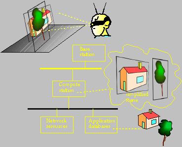
Figure 4. Overview of rendering system.
As the image imposters have only a short life time (only accurate near the initial view point), new imposter updates will have to be generated at the compute station and sent to the mobile unit. Together with the latency-layered tracking, this gives us the following latency-layered structure (Figure 5). The image is updated each 10ms after a user moves, but with only an approximate image. More accurate updates (over the mobile link) are available only after 100ms and 1 second.
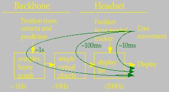
Figure 5. Latency-layered structure of the system
3. Scene representation within the mobile unit
As discussed above, the mobile unit will hold only simplified versions of the scene. A number of possibilities are open here. We consider simplified polygon objects, meshed imposters, images with depth, and simple imposters. See Figure 6.
Figure 6. Several simplifications of the cow model: simplified polygon object, meshed imposter, image with depth, and simple imposter.
Simplified polygon models seem a good choice to replace nearby objects, because the observer can move around them freely without requiring the system to refresh the model. But for distant objects this is overly accurate, as the observer will probably never see the back faces.
Another option is to use simple imposters. For nearby objects this is not a good choice, as the texture on the imposter would have to be updated very often and because the poster is only correct for a small region around the initial view point. But for distant objects this seems a good choice.
The meshed imposter and image with depth seem suited for the inbetween cases: they are more accurate than simple imposters and therefore can be used longer, but they still have no back faces.
This analysis suggests the configuration of Figure 7 nearby objects are represented with simplified polygon models, more distant objects with images with depth or meshed imposters, and far away objects with simple imposters. The switching distances may be closer for objects outside the viewing cone of the observer, to avoid too much effort being put in rendering things the user is not looking at.
Figure 7. Intuitive way of using various objects with varying distance.
However, for deciding which representations to use for which objects in order to stay within the limit of a few hundred polygons/imposters, we need a model that tells us how to trade-off accuracy against the memory and rendering capacity at the mobile unit and the latency of the mobile link. We did a thorough analysis of the various techniques, to estimate the accuracy as a function of the number of polygons and the load they impose on the wireless link. This model is too large to discuss here (see [Pasman2003]). Figure 8 shows the relative performances of the simplified polygon model (red), meshed imposter (light blue), image with depth (purple), simple imposter (green).
.
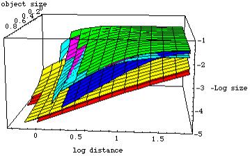
Figure 8. Model size as a function of the distance to the object and the size of the object. Lifetime was set to .1 second.
We can see that the imposters are very close in size, and that the polygon model is much larger but does not grow as fast with decreasing viewing distance. All models break down at some point: at closer distances the model cannot reach the distortion and life time requirements anymore. The simple imposter breaks down earlier than the other models, because it is very much confined to the initial view point. The polygon model also breaks down at some point, because we have a limited amount of polygons and distortions will become evident anyway if the observer comes close to the object within the life time of the object. In this case, a near clip distance will have to be defined to avoid excessive model refresh.
As the model size is a function of the chosen life time (refresh rate), we can find the average link load by dividing the modelsize by its life time (Figure 9). The meshed imposter has a slightly longer lifetime at a given maximum distortion than a simple imposter, but essentially only a polygon model can reach the distortion requirements at close distances. At 17 GHz, the mobile link does not put a limitation on the transfer of model data, however, the latency of about 100 ms strongly limits the use of simple imposters because at realistic life times of 100 ms for nearby objects, the link can not provide fast enough updates form the compute station.
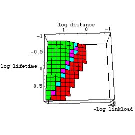
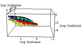
Figure 9. Load on the wireless link as a function of distance to the object and the lifetime. The distortion D=0.005 rad, the polygon budget N=1000 polygons and the object's size r=1 meter.
The results of our estimation of the load on memory and CPU is straightforward: as the number of polygons in our system will be much smaller than the number of pixels to be put to the screen, the main CPU and memory load follows from the amount of pixels in texture memory and on the screen. Therefore, the main load comes from the way these pixels are stored (are they RGB, RGBA or RGBA + depth), and the amount of per-pixel calculations (images with depth require additional per-pixel warps and splat kernel calculations). Simple imposters, meshed imposters and polygon models all impose very similar loads. For images with depth this depends on the rendering method, ranging from a 33% higher CPU load for forward splatting to a 60% higher CPU load plus a 100% higher memory load for a hybrid mapping.
Concluding, the intuitive sketch of Figure 7 seems confirmed by our theoretical model, although the exact boundaries require some refinement of the model and some experimental testing.
4. Conclusions
We discussed our latency-layered approach to meet the high requirements for mobile augmented reality, and we sketched an approach for deciding which model representations are appropriate for the mobile unit. The presented analysis suggests that simple imposters are appropriate for distant objects, meshed imposters can extend their life slightly, and that polygon models are required for nearby objects.
Publications
R.L. Lagendijk, "The TU Delft research program Ubiquitous Communications", Proceedings of the 21th Symposium on Information Theory in the Benelux, pp. 33-44, 2000. pdf
Pasman, W. , Schaaf, A. van der , Lagendijk, R.L., & Jansen, F.W. (1999). Low latency rendering and positioning for mobile augmented reality. Proceedings of VMV'99 (November 17-19, Erlangen, Germany), 309-315. pdf
Pasman, W., & Jansen, F. W. (2001). Realistic low-latency mobile AR rendering. Proc. VAA01 (Trinity College, Dublin, Ireland, 21-22 June), 81-92. pdf
Pasman, W., & Jansen, F. W. (2001). Distributed Low-latency Rendering for Mobile AR. Proc. IEEE & ACM Int Symp on Augmented Reality (ISAR'01, Oct 29-31, Columbia University, NY), 107-113. pdf
Pasman, W., & Jansen, F. W. (2002). Scheduling Level of Detail with Guaranteed Quality and Cost. Proc. Web3D Conference (February 24-28, 2002, Tempe, AZ), 43-51. pdf
Pasman, W., & Jansen, F. W. (2003). Comparing simplification and image-based techniques for 3D client-server rendering systems. IEEE Transactions on Visualization and Computer Graphics, 9 (2), 226-240. pdf